

July
2023
Part 2: Modes, protocols, and firmware
Well well well, back for more eh? Did my previous blog post interest you? Want to learn more about these mysterious devices? Or just accidentally clicked a link and have no idea how you got here? Then this is the blog post for you! This is the second in a multi-part series where we take a deep-dive into the wonderful world of payment terminals A.K.A. card machines A.K.A. card readers. If you haven't read my previous blog post, then go back and read it HERE first! You wouldn't start Harry Potter with the Chamber of Secrets would you?
In the last blog post we looked at the hardware inside an Ingenico iPP350 payment terminal, and what happens if you crack one open like an egg.
This time we'll be looking at the software side of things, including:
- The multi-layered trifle of software components running on the device
- The types of files that the device uses
- The different modes that the device can operate in
- How to communicate with the device using these modes
- How I used one of these modes to extract the contents of flash memory
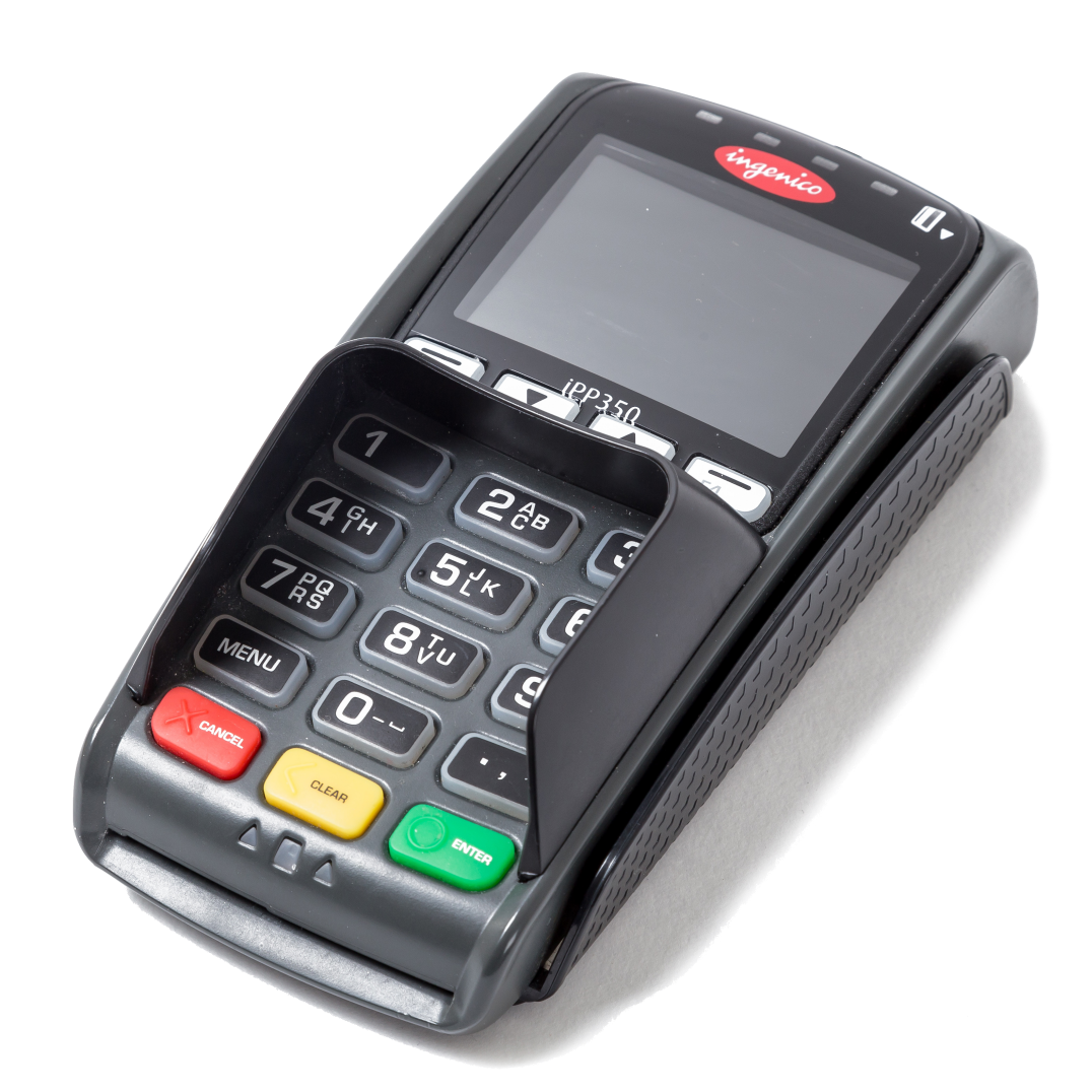
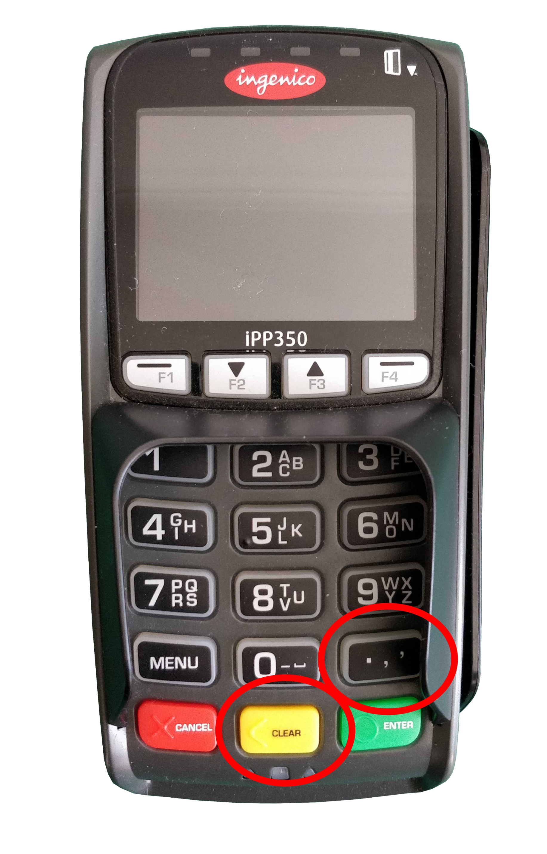
In case you've forgotten what the payment terminal looks like, here it is in all it's glory:
The Software Stack
The trifle consists of three main components:
1. Bottom layer: Telium 2 OS
Telium 2 is the operating system that the majority of Ingenico's previous generation of payment terminals run on, first introduced around 2008 (the latest generation of terminals use a new OS called Telium Tetra, but that's a story for another time).
The Telium 2 OS is responsible for performing all of the functions that a standard operating system does. This includes things such as handling the memory requirements of applications running on the device, and providing the applications with a means of accessing the device's low level software and hardware components such as:
- File System
- Memory Management Unit (MMU)
- Keyboard/Display/Printer
- Magstripe reader
- MMC/SD Card
- Ethernet/MODEM
- USB/Serial/COM interface
2. The gooey middle: Telium Manager (M2OS)
Telium Manager (also known as M2OS) is an application found on most Telium 2 devices. This application is responsible for handling various configuration and diagnostic settings, such as:
- Application management
- Terminal initialization
- Terminal maintenance and configuration
- Choosing which application to use to process a transaction
- Inter-application communication
When an event occurs on the device (such as a key being pressed, a card is inserted, a file is received, etc.) Telium Manager detects this, chooses which application to switch to, and which function in the application to execute. Functions in an application that are exposed to Telium Manager are called "entry points". Depending on the version and device model, Telium Manager can appear in one of three ways:

3. Choose your own topping: Applications
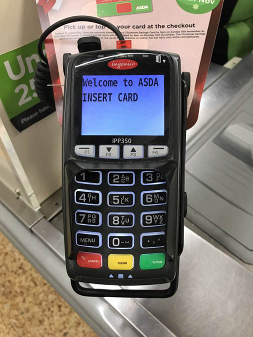
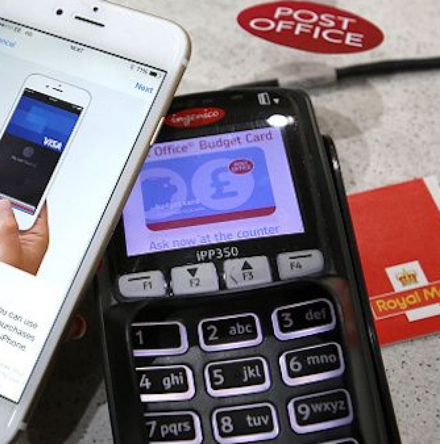
Often when you use a payment terminal in a large supermarket, the payment terminal will show text and images that matches their branding. As well as performing transactions, they may carry out additional actions specific to that supermarket, such as displaying ads or asking for a rewards card. To accommodate this, Ingenico provides support for their customers to develop their own applications that can be run on their payment terminals.
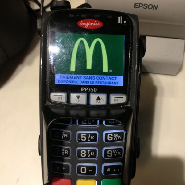
Applications can include custom text and images, and can be in black and white or colour depending on the card reader model.
However, Barry the local butcher from down the street wants a card machine too, but he's too busy carving up tasty sirloins to be writing his own custom applications. Thankfully, Ingenico provide two of their own so Baz doesn't have to become a software dev on the side.
RBA and RAM
The two applications that Ingenico offer are RBA (Retail Base Application) and RAM (anyone who can find me what RAM stands for wins my eternal admiration and respect). RBA is provided for terminals operating in North America, and RAM is it's European equivalent.
Lord of the Files
Telium 2 payment terminals support six types of executable files:
Each of these files include a 224 byte plaintext header called a descriptor. The descriptor descriptively describes various details about the file, such as the file type, size (compressed and uncompressed), encryption method (if used), human-readable name, and many more tasty nuggets of info. You can find a description of the descriptor in the appendix at the bottom of this post. It's very descriptive.
Now we've looked at the way the device software is structured, lets have a look at the different ways the device can operate.
Device Modes
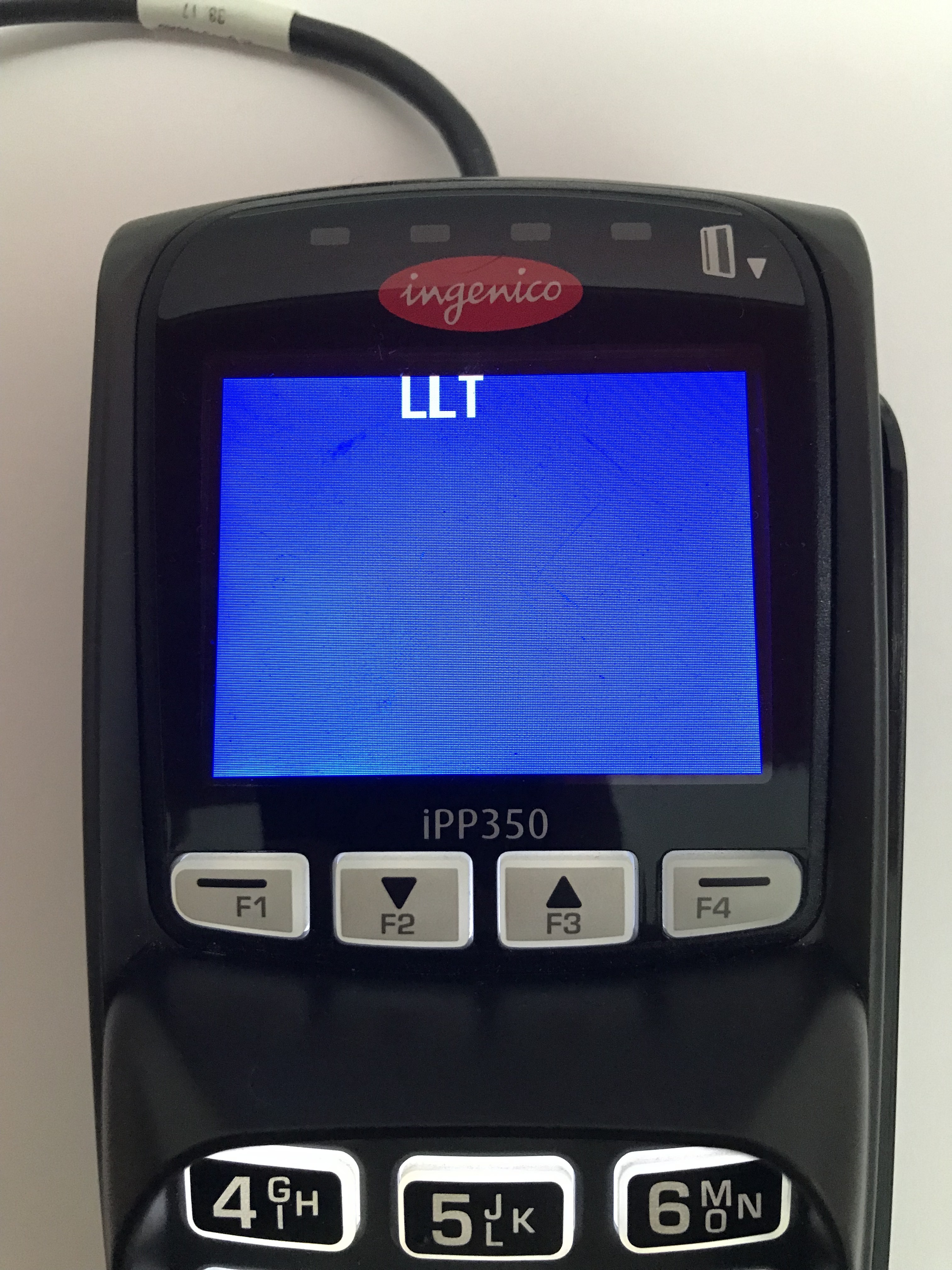
The iPP350 has two modes that it can operate in to achieve different goals. One is called LLT (Local Loading Tool) mode, and the other is called Trace mode.
LLT Mode
When the device is booted into LLT mode, the device can be accessed using the Local Loading Tool, a windows program created by Ingenico.
The LLT program is used for three purposes:
- Uploading files/applications/updates to the device
- Listing currently installed software
- Listing device properties (i.e. model, memory usage, hardware details etc.)
As well as applications, the Telium OS and Telium Manager program can also be updated using this method. It is through this method that custom applications/images/videos can be uploaded too. However, all custom files must be signed by Ingenico first before it can be uploaded onto the device. Sorry to all those who wanted to run Doom on it.
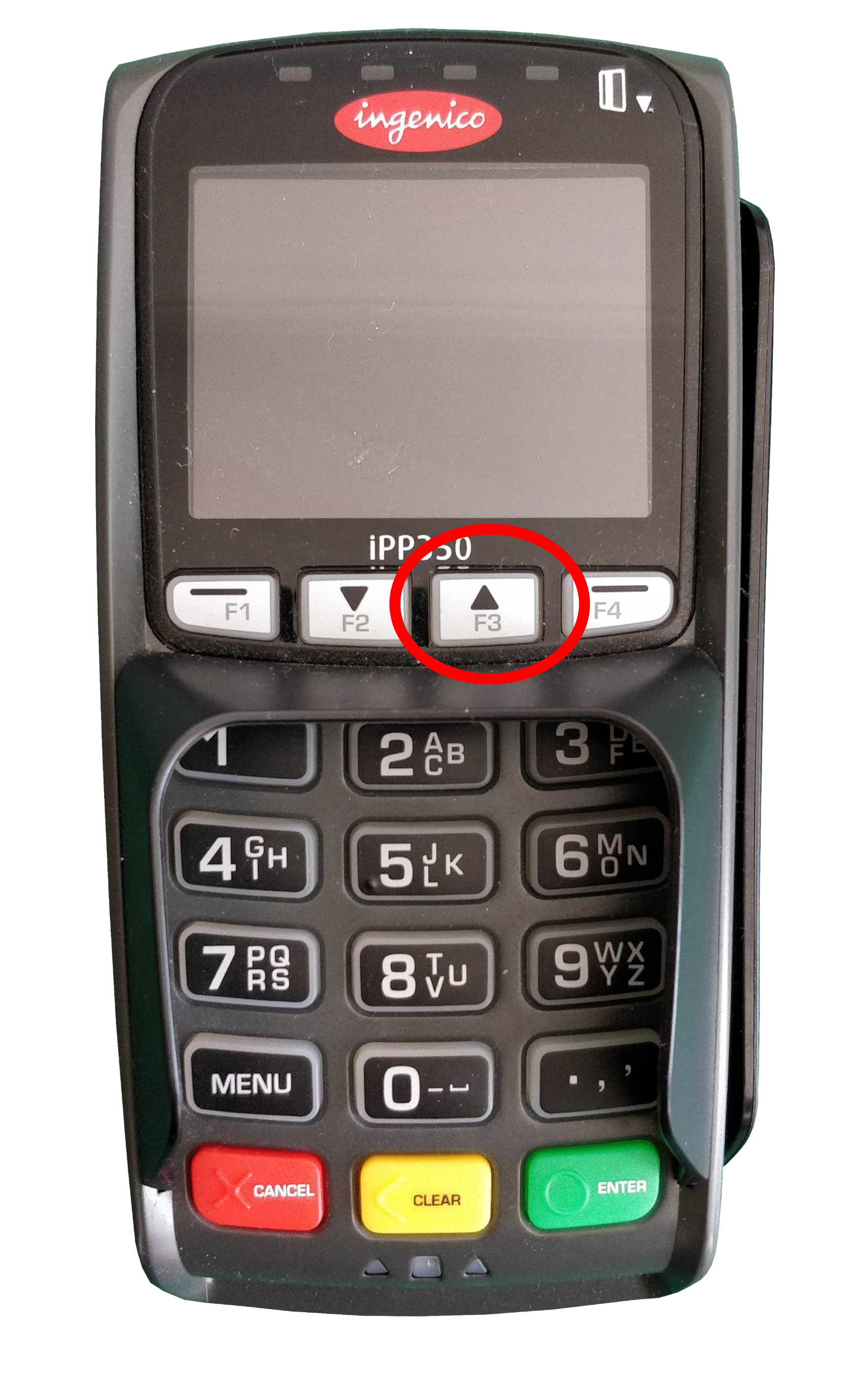
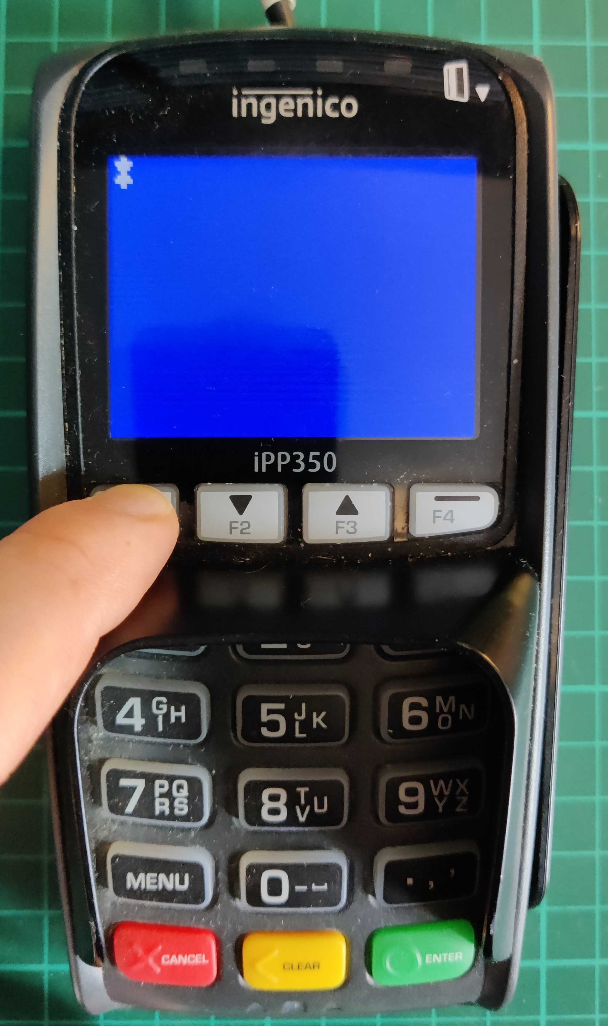
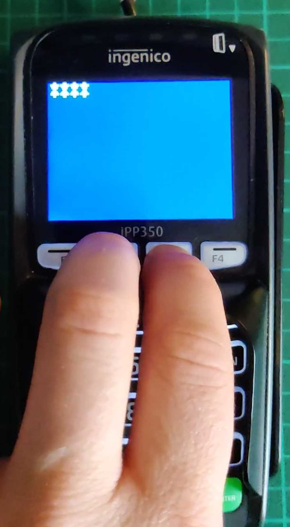
To boot the terminal into LLT mode, perform the following steps:
The types of files available to the user when using LLT is defined by which "Activity" context is chosen. There are three of these:
Once the terminal has been started in LLT mode and is connected to the LLT tool, the user is able to interact with a file system on the device, which consists of only two folders:
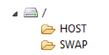
The HOST folder is used to load parameter (.PGN) files onto the terminal, and the SWAP folder is used to upload all other application files. SWAP is just a temporary folder, the contents of which get moved into the /SYSTEM folder (which is not visible from the LLT tool) onto the terminal after the LLT connection is closed. This behaviour is likely implemented as a security measure, as it enforces a one-way system to prevent users from extracting potentially sensitive files from the device's /SYSTEM folder.
Total Wipeout
One thing I wanted to check while playing with the terminal was what files remained on the device after a system wipe. And before you ask, yes, I made a backup of the installed components before doing this (more on that later 😉).
The process of doing this differs slightly depending on which Telium 2 terminal you are using, but for the IPP350 it is as follows:
Once the device had been wiped, I connected to the terminal in LLT mode and asked it very nicely to list the currently installed components. The terminal returned the following results:
As you can see the name of each file is completely numeric, and all three are driver (.DGN) files. The last four digits of the filename tells you the version (two digits for major version and two for minor). Everything before that is a unique file ID.
But if I asked the terminal to completely wipe itself, why are these three files still present? Does the terminal pick and choose what to delete? Who's in charge here?
To find out what these files are, I wrote a Python tool using Kaitai Struct (a great tool you should check it out) to parse the structure of the descriptor from executable Telium 2 files and display it in human readable text. Running the first file through this tool produced this:
The friendly_name field in the descriptor tells us that this file is called System Telium Thunder Plus, A.K.A. the Telium 2 OS that runs on the Thunder microcontroller. Using this tool on the other two files revealed that the friendly name for 30140503.DGN is Boot ram thunder 0503: the device's bootloader, and 30210325.DGN is Driver VFS: a driver file which presumably handles the device's virtual file system.
Makes sense why we couldn't delete these files earlier now doesn't it? The OS, bootloader and file system are the bare minimum components required for the terminal to function, otherwise it would just be a fancy looking paperweight.
So how does LLT Mode work?
When I connected the terminal to my PC via USB, it appeared in Device Manager on Windows as a COM port. When I used Linux, it appeared in dmesg as /dev/ttyACM0. This indicated that the terminal communicates using a serial connection.
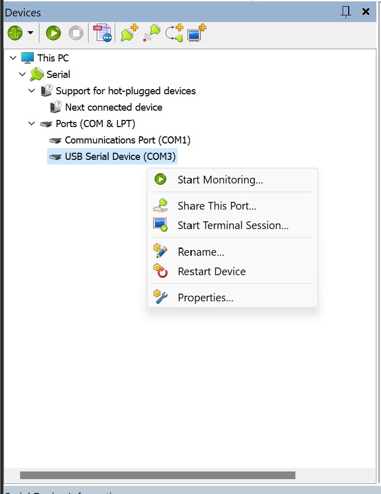
In order to reverse engineer the traffic between the PC and the terminal, I needed to find a tool that would be able to monitor the serial device connection and display the transmitted data. As the LLT tool is windows only, I chose to look for one that was written for windows rather than faff around with redirecting the connection through a Linux virtual machine. After a thorough look at the smorgasbord of slap-dash half-baked no-good two-bit "My first Visual Basic GUI" serial connection monitoring tools out there, I settled on HHD's Device Monitoring Studio. This one actually had a usable UI, worked intuitively, and didn't cost more than the GDP of a small country. Once I had chosen the COM port that the terminal was assigned to, selected the monitoring software's "data view", and started the connection from the LLT tool, I was able to observe the raw bytes sent to and from the terminal.
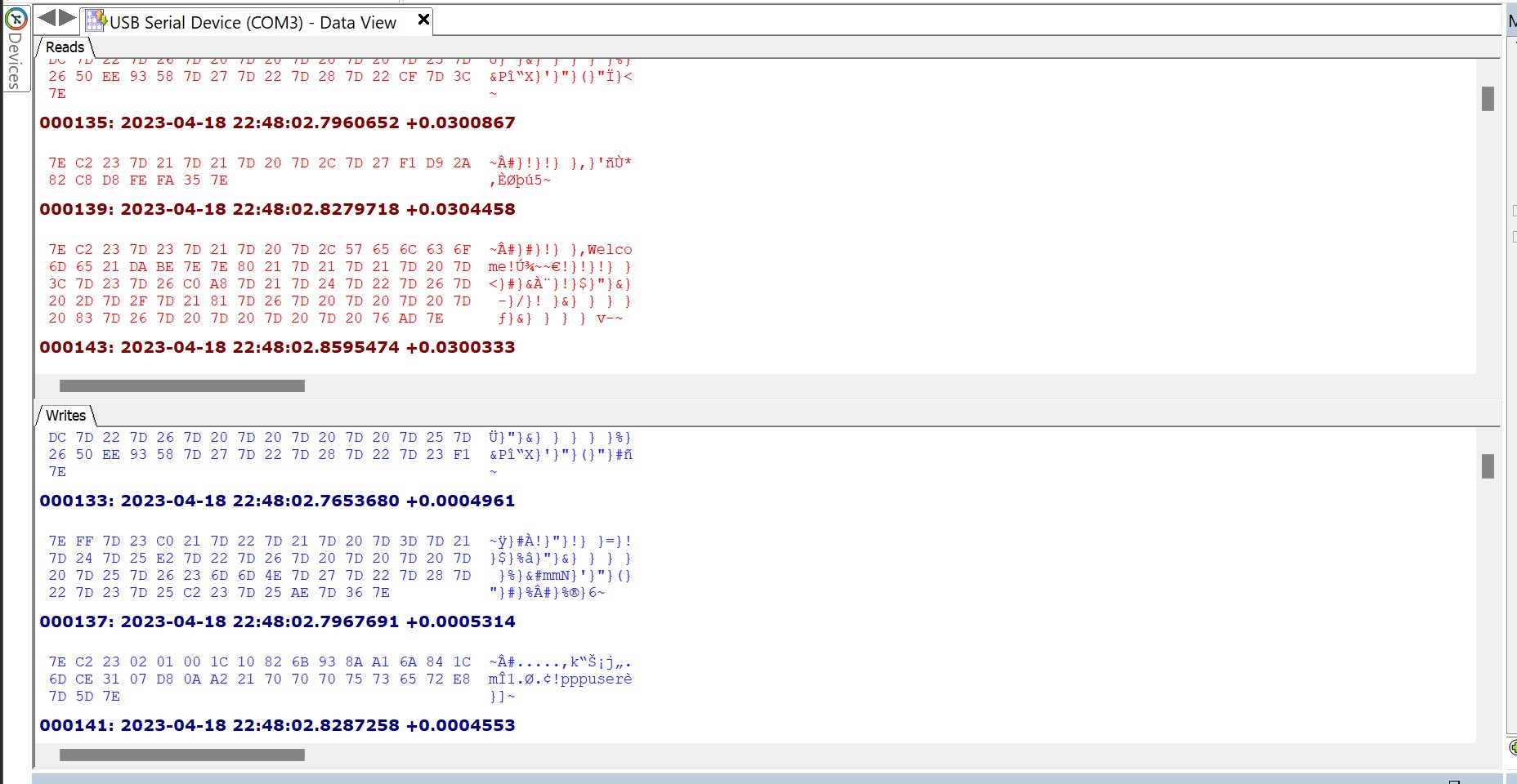
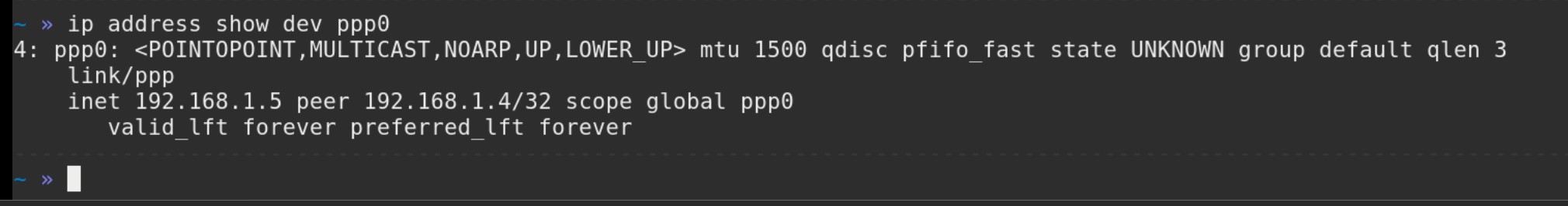
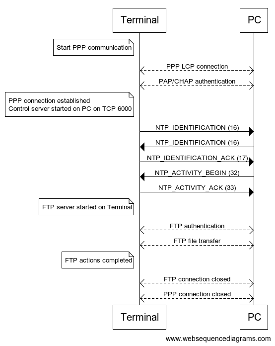
The serial monitoring tool was able to identify that the connection used a baud rate of 128000, which I thought was weird as it's not one of the common baud rates you normally come across. Examining the captured raw bytes showed that each "packet" of data started and ended with the byte 0x7E. After some searching I found that this was likely to be PPPoS (Point to Point Protocol over Serial). When connecting to the terminal using the Linux tool pppd (Point to Point Protocol Daemon) the terminal asks for authentication. Fortunately, the LLT tool sends the PPP credentials in plaintext: username pppuser and password 123456. These hardcoded credentials were reported in CVE-2018-17767. Once authentication is complete, a PPP network interface is opened on the host, which is then assigned an IP address by the terminal.
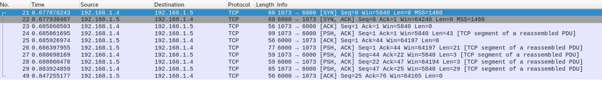
Examining this connection with Wireshark revealed communication over TCP on port 6000. Wireshark was not able to identify a known application layer protocol using this connection.
By analysing the raw TCP payloads, I found that the unknown protocol uses a TLV (Tag Length Value) format. As the name would suggest, this format is comprised of three parts. The first byte is an identifier for the packet type (the Tag). The second byte (the Length) denotes the number of bytes remaining in the payload, which contains the transmitted data (the Value). Examining the Wireshark capture, and also doing some reverse engineering on the LLT tool itself, I was able to find that this is a proprietary protocol created by Ingenico called NTP. What this stands for is unclear, but my money is on something like Network Transfer Protocol.
After a bit more prodding and poking, I was able to find the various commands that this protocol supports:
The NTP_IDENTIFICATION command contains various details about the device sending the command, such as the NTP protocol version used and the device model, serial number, etc. When NTP communication starts, the first thing that happens is both the PC and Terminal send this command to let each other know what they are. Basically the equivalent of two really eager dogs sniffing each other's rear ends.
The NTP_ACTIVITY_BEGIN command contains a value denoting which of the three previously mentioned "Activities" the LLT tool will connect in. They've also thrown in a "no activity" value in case you just want to say hello. How friendly!
If you are deemed to be worthy of an audience with the terminal, it will respond to the "identification begin" and "activity begin" commands with the corresponding ACK commands.
Once all the NTP flirting has finished, the terminal starts up an FTP (File Transfer Protocol) server on standard TCP port 21. It is through this FTP connection that all of the LLT functionality is carried out. Files are transferred via this method (obviously), and the device characteristics are read by downloading the two files TERMINAL.CNF and ACTIVITY.INF. By observing the FTP traffic between the LLT tool and the terminal, it is possible to read the FTP server banner message, which explains that the FTP server used is NexGenREMOTE FTP server (version 1.0). The LLT tool then provides (also in plaintext) username ftpuser and password 123456. These hardcoded credentials (along with others that the FTP server accepts) were disclosed publicly in CVE-2018-17771.
So in total, we have FTP and NTP over TCP over IP over PPP over Serial. Over the top if you ask me.
The whole thing looks roughly like this:
Trace Mode
In 2020, researchers at Cyber R&D Lab published a paper titled POSWorld: Vulnerabilities within Ingenico Telium 2 and Verifone VX and MX series Point of Sales terminals. In this paper they describe a method of configuring an IPP350 so that it runs in another mode called Trace mode. According to the paper, the purpose of Trace mode is to "monitor performance of banking applications during their development" and "It assists developers with debugging and post-debugging processes".
This method of enabling Trace mode was subsequently reported and given the CVE number CVE-2018-17772. This means that due to an update released by Ingenico, this method is only possible on older versions of Telium 2 OS. So pick your terminals carefully!
In order to enable Trace mode, you must boot the device into LLT mode, then use the LLT tool to upload a config file called SYSTEM.CFG into the devices /SWAP directory. You must then reboot the device so that it boots into it's normal operation mode.
The contents of SYSTEM.CFG is only two lines:
TRACE_DEV=5
LDBG_DEV=0
Once I had done this and the device had booted into normal operation, I tried connecting to the terminal with PuTTY, and monitored the connection using Device Monitoring Studio. Using a standard baud rate of 115200, I was immediately bombarded with output that contained a mixture of ASCII data and other unreadable garbage.

If the terminal has been wiped so that it always boots into LLT mode (i.e. no applications are installed), then Trace mode doesn't work. This is because it is only enabled once the device boots into it's normal operating mode. After spending more time looking at this raw data than it takes to watch all the Fast and Furious movies, I finally started to see method in the madness. It's just another TLV structure again! This time though they've used two bytes for the header field to define what type of message it is. The structure looks like this:
Now that I was fluent in trace-modeese, I wrote a Python script to try and send a message of every packet type to see if I would get a response (the equivalent of saying every word in the dictionary until someone talks to me). Out of all the message types only one actually had a meaningful response. By sending a packet with message type 0xEE0C, the terminal would respond with a message of type 0xEE02 containing ASCII text. I then wrote ANOTHER Python script (this is becoming a habit) which would take input and send it in an 0xEE0C packet, and display the payload of the responding 0xEE02 packet. The result was this:
Gadzooks! It's a shell! It turns out that Trace mode contains an interactive shell that lets the user examine certain things about the device, such as its file system, installed drivers, power management, and internal memory. I've added the entire menu tree in the Appendix if you'd like to have a gander.
Typing fs takes you to the File System (or maybe Flash System?) submenu:
This submenu has some VERY interesting commands available, such as list, which recursively prints out the name of each directory and the files that are inside them, including ones that are not accessible from the LLT tool.
Based on the output from this command, the entire file system looks like this:
If I had to guess, the /MANAGER and /MGR_RECEPT folders relate to Telium Manager (M2OS).
Another useful command map lists information about the terminal's flash memory, including partition sizes and their address ranges:
It looks like the APPLI partition might contain the .AGN files that can be loaded onto the device using the LLT tool, and the BOOT_RAM partition will probably contain the bootloader. I found that each page of memory has it's own ID, so the IDENT folder may be where those mappings are stored.
This flash info explains that the flash chip is 128Mb in size, and is made up of 1024 blocks that are each 128Kb. Each block contains 64 pages of memory, and each page is 2048 bytes. That's a lot of numbers so here's a visual representation I made in Excel.

My favourite command out of the bunch though would have to be dump. Sending the command dump <address> prints out a page of memory starting from the given address...
... and typing enter automatically dumps the next page of memory.
This means that I can dump the entirety of the terminal's flash chip over the command line! And that's exactly what I did. I wrote another tool (in Python) to read this serial data, strip out any unnecessary characters, and save the resulting data to a file. MY GOD did it take a long time. Each time you run the dump command, there would be a slight delay while it executed, followed by outputting the result over the serial connection to the terminal. And 64 pages x 1024 blocks = 65,536 pages! I left the tool to run overnight, and had it finished when I woke up the next day? Nope. Dumping the whole flash chip ended up taking NINETEEN AND A HALF HOURS. It was worth it though, because at the end of it I had this:
Wow would you look at the time, we've reached the end of the blog post! I hope you've enjoyed getting to know this payment terminal better, at this point I reckon if you bumped into one on the street you'd at least be on a first name basis with it. If you've managed to read all the way to this point, you've now (hopefully) got a (slightly) better understanding of the software internals of a payment terminal. We've looked at how the firmware is structured, how the device can operate, how useful hardcoded credentials can be (more of that please), and what you can do if you look at a load of hex numbers REALLY closely. These were all important steps that culminated in successfully squeezing the flash memory contents out of the device. But now we have it, what do we do with it? Stay tuned to find out in the next blog post, where we'll take a look at:
- How to extract the partitions from the memory contents and what these partitions contain
- How executable files are structured
- How I reverse engineered the algorithm used to compress these executable files
- Tiny functions called "schemes" responsible for performing secure operations
And maybe we'll even disassemble some files using IDA to see what we can find.
To quote the wise and erudite philosopher Victoria Justice, who was clearly referring to payment terminals: "What really matters is what's on the inside."
